UBC Supermileage
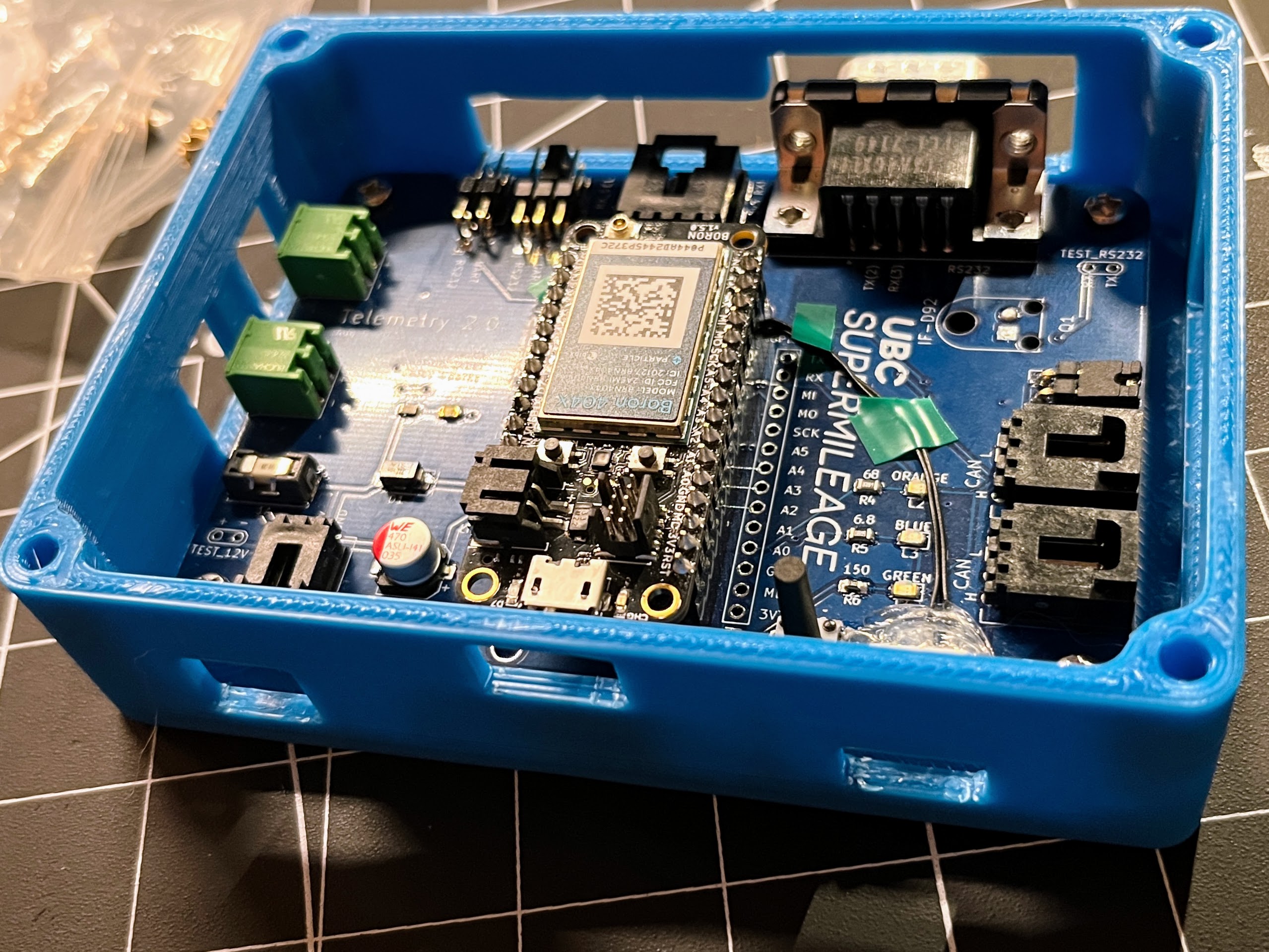
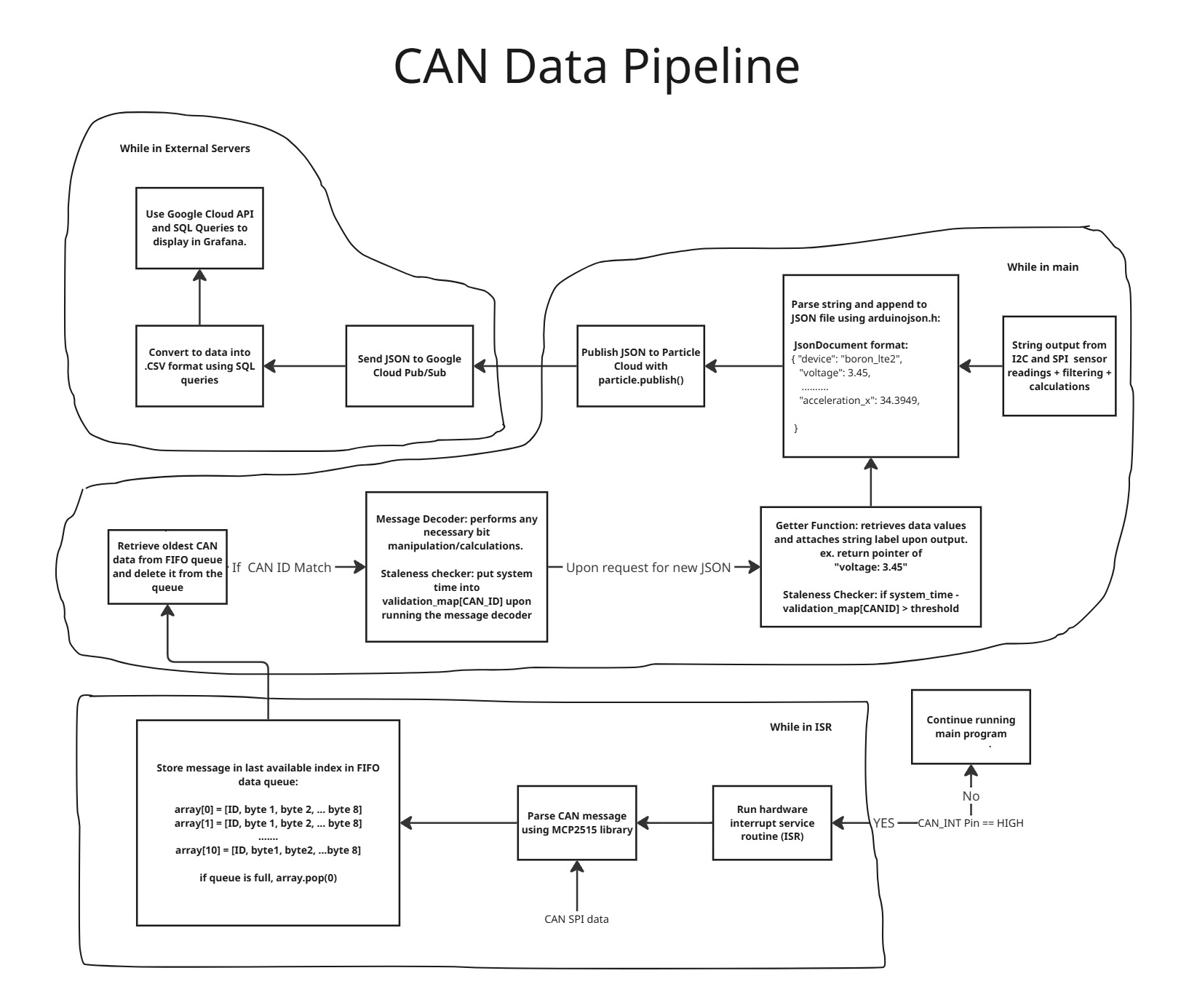
As part of the UBC Supermileage car team, I helped design and program a telemetry system that allows the team to gain access to sensor data useful for improving the overall design of our cars. Our team annually participates in the Shell Ecomarathon (SEMA) in three different vehicle categories (Gas prototype, Urban EV, Hydrogen Fuel Cell), where we compete against other universities across the world to see who has the most efficient vehicle. Our telemetry system collects important sensor data such as speed, rpm, GPS location data, temperature, and acceleration through various sensors onboard the PCB as well as other electronics connected to the CAN bus. The PCB is centred around a Particle Boron LTE module, which contains a Nordic Semiconductor nRF52840 microcontroller. The peripheral features on the PCB include a CAN transciever, accelerometer, and numerous ports that connect to the ECU, Driver display, and GPS. The same telemetry board can be used for all three vehicle types, but the peripheral connections and firmware differ depending on the car (ex. engine ECU for gas, electric motor driver for EV). Our data is transmitted in a JSON format from the Boron LTE module to Google Cloud, and from Google Cloud to Grafana Dashboards, where we visualize and monitor the data in real time.
What I am currently working on:
- Extended Kalman Filter implementation using the BNO055 9-dof IMU and GPS module
- Designing a magnetic encoder based steering angle measurement setup
- Debugging hardware/software issues
- Use of extra sensor connectors allows for more versatility, allowing telemetry to adapt to three different vehicle setups.
Links:
Check out our firmware repository: Firmware
Check out our team website: Team Website
No Polygons
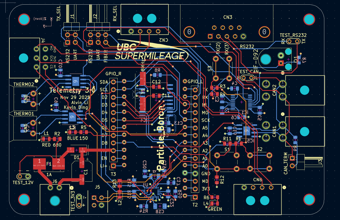
Top Signal
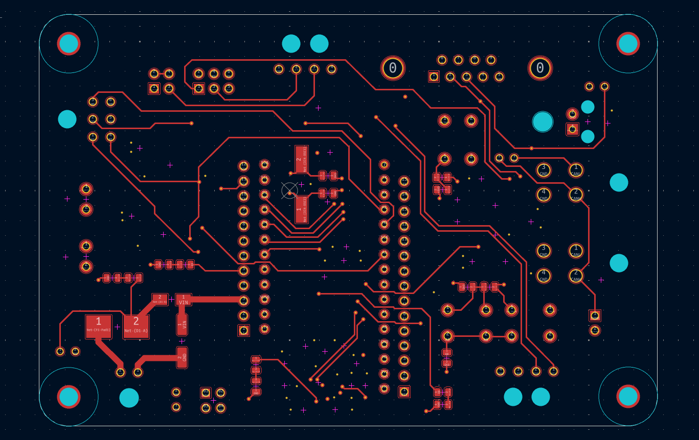
Ground
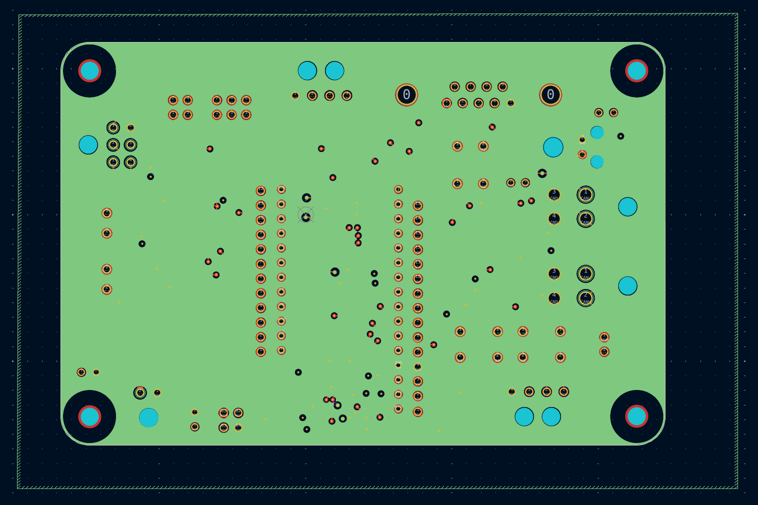
Power
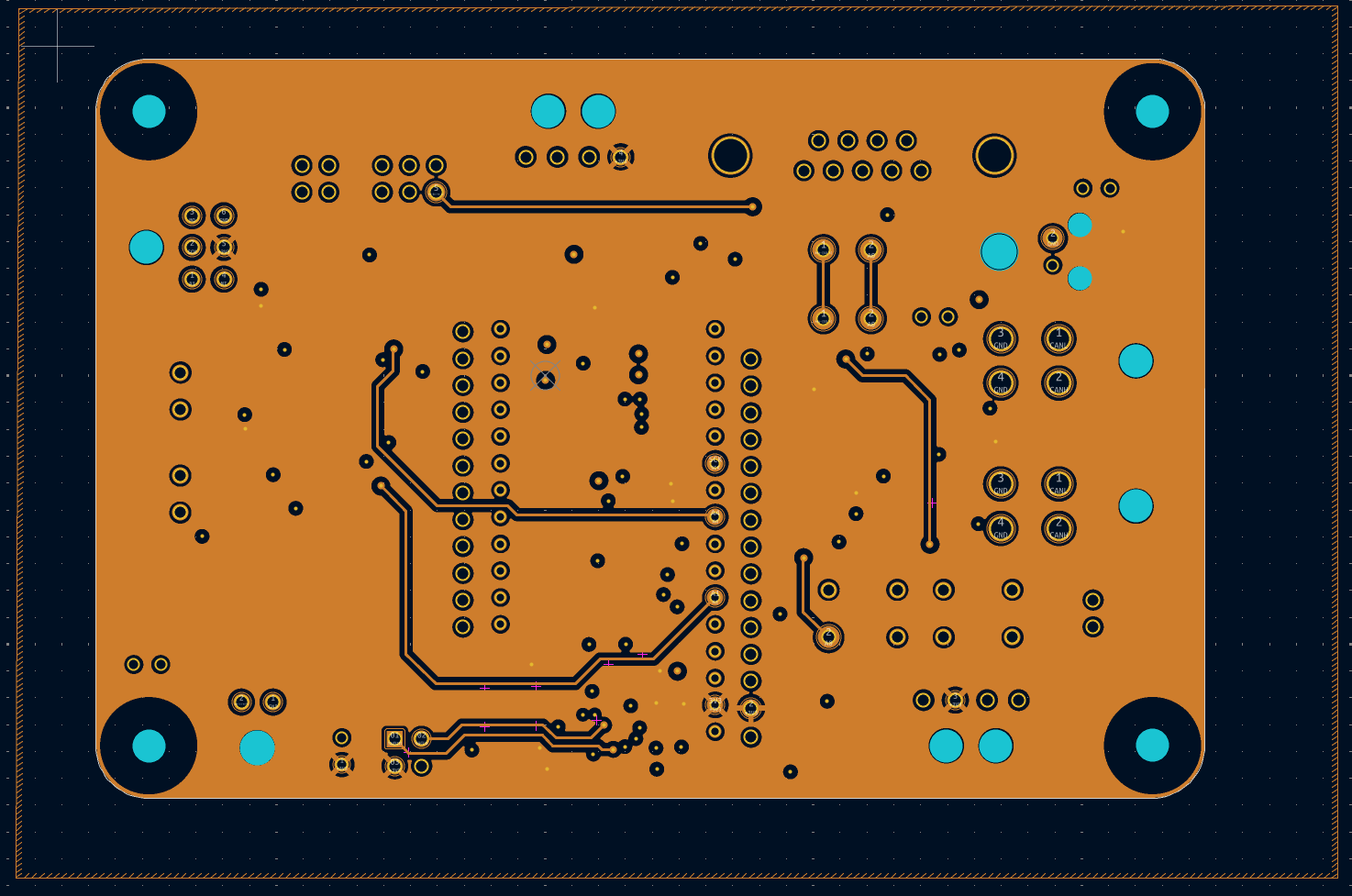
Bottom Signal
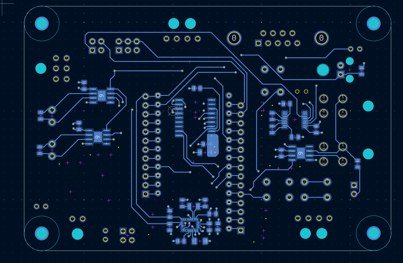
Some Design Considerations:
- 4-layers to help prevent signal integrity issues and easier routing
- Fuse for overcurrent protection
- Multiplexing buttons, I2C and SPI busses to enable more functionality with the same pins
- 9-axis IMU vs the old 6-axis IMU, results in much better accuracy thanks to the gyroscope and sensor fusion
- Extra SPI connector for SD card logging implementation
- Avoided 90 degree turns if possible as a safety precaution
- Utilized molex minifit connectors for the CAN bus, matching all other PCBs onboard the vehicle
Boron
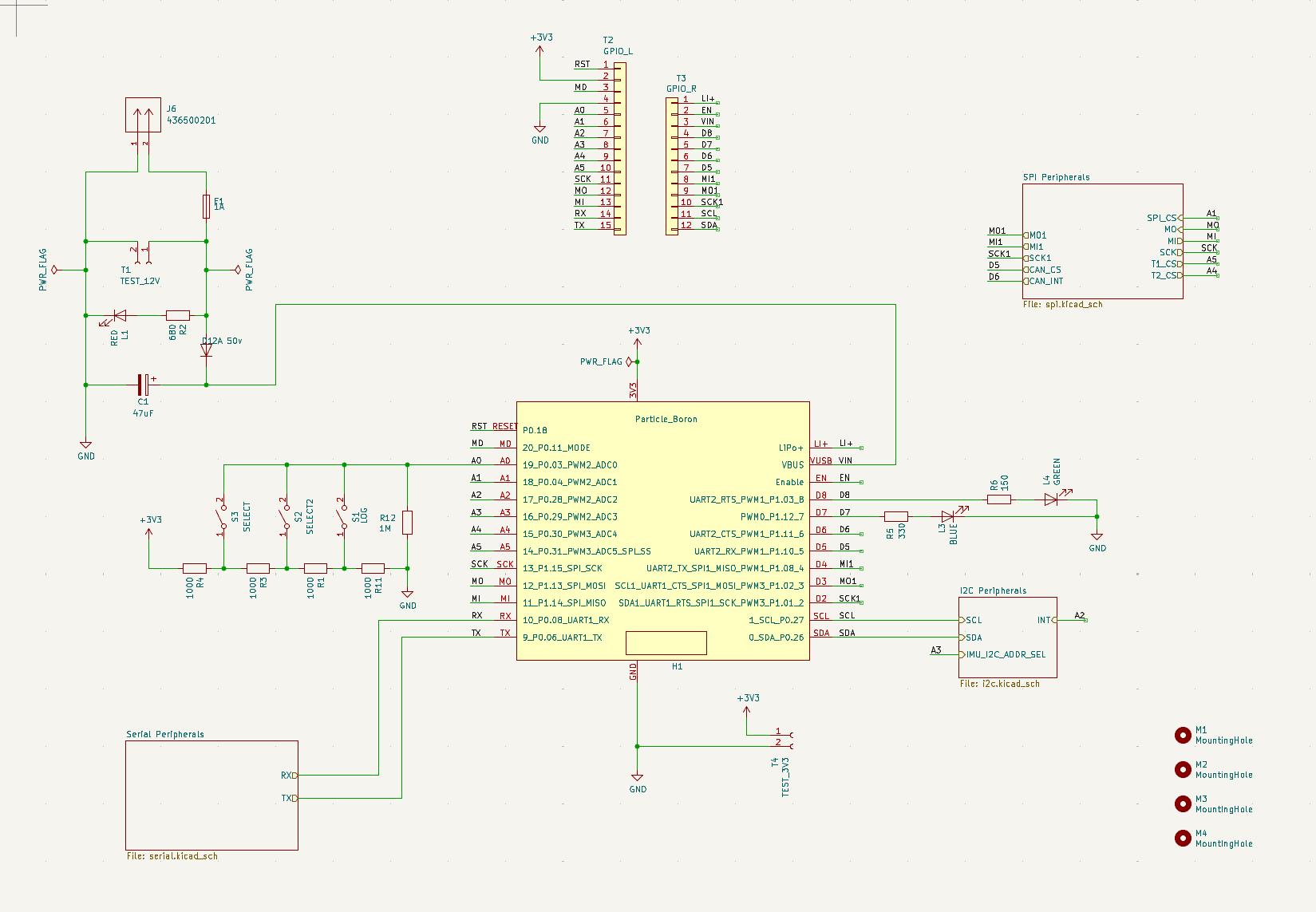
- Parent schematic includes the LTE modem and 12V power input
Telemetry RS232
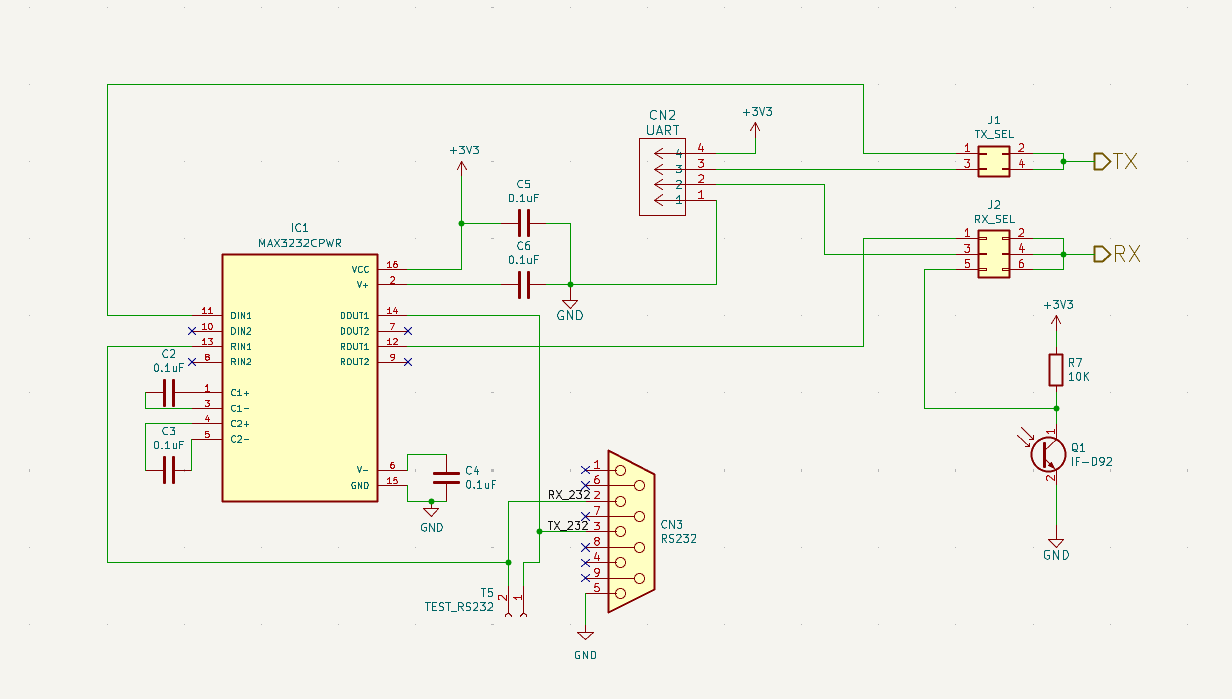
- MAX3232 allows the MCU’s UART to interface with the computer by conversion to RS232 protocol
I2C Peripherals
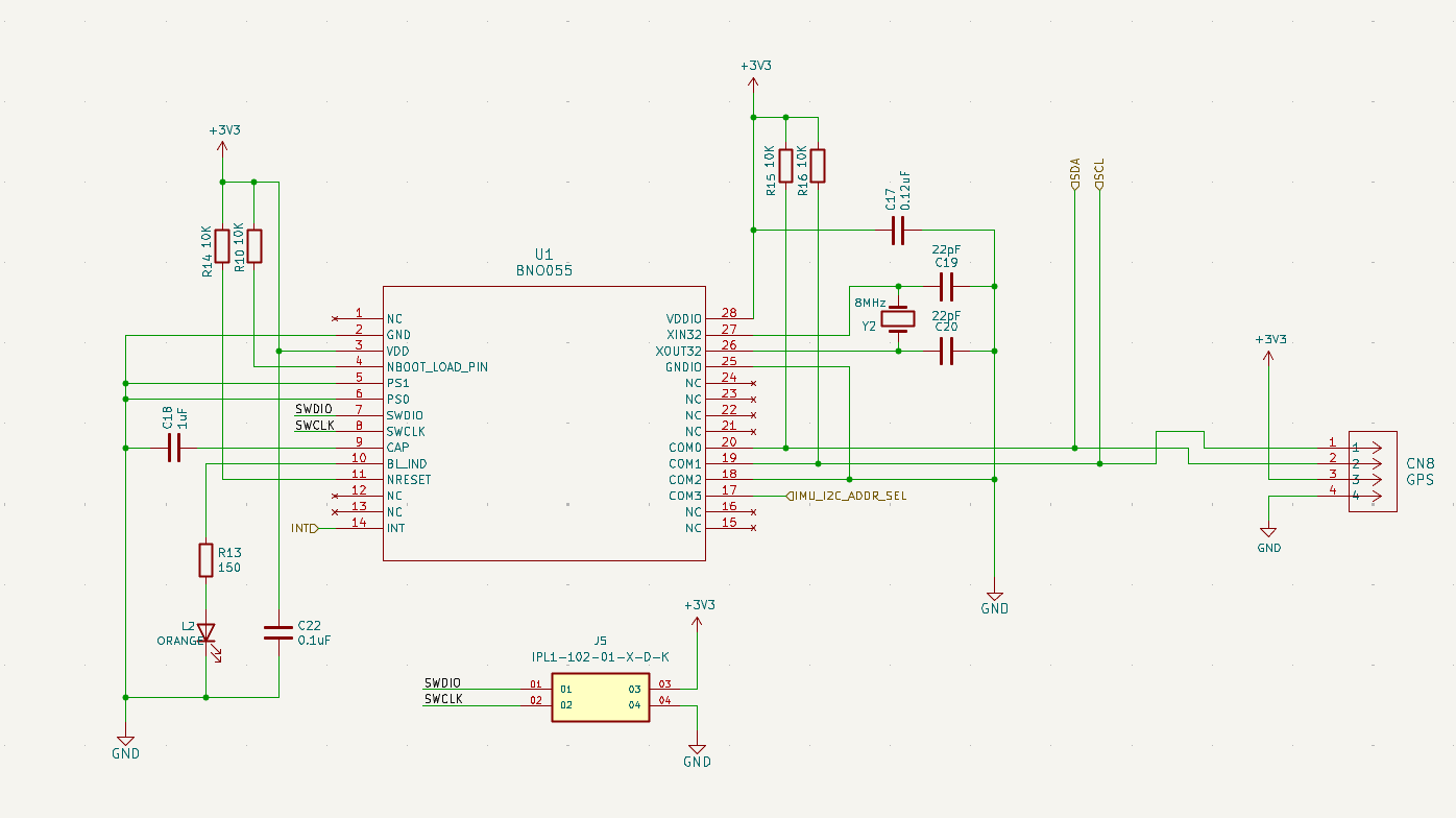
- Multiplexed IMU and GPS on the same bus
SPI Peripherals
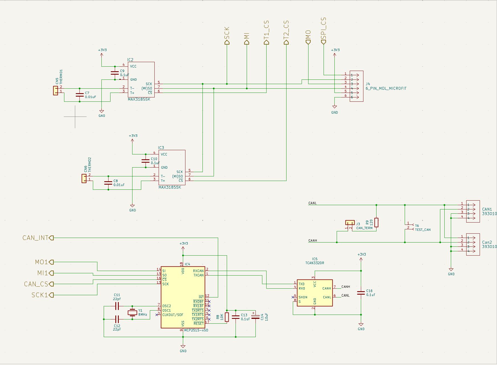
- SPI connector, CAN controller and thermistors are multiplexed
- 120 ohm resistor configurable in case the telemetry is at the end of the CAN bus
Data Pipeline Example for CAN