Personal Drone Project
Drone ESC
Brushless motor ESC designed from scratch for drone use, aiming for 6s to 8S battery input using Field-Oriented Control (FOC). Fits the standard 30.5mm x 30.5mm mounting hole pattern used in FPV frames.
Key Design Decisions
Microcontroller: STM32G431KBT6
Chosen for its built-in CORDIC accelerator (Park/Clarke transforms), dual ADC for simultaneous phase current sampling, and TIM1 with 6 complementary PWM outputs. Hardware deadtime insertion prevents shoot-through. The QFN-32 package also fits within the 30.5mm form factor. In order to communicate RPM date with the flight controller, it uses DSHOT via one of the PWM outputs.
Gate Driver: DRV8323S
SPI-configurable three-phase gate driver with integrated charge pump, bootstrap circuitry, and three CSAs with selectable gain (5x/10x/20x/40x). Runtime configuration of gate drive strength and overcurrent thresholds via SPI avoids hardware respins during tuning.
Power Stage: CSD18532Q5B MOSFETs
60V, 100A rating N-channel MOSFETs, which should be enough to handle a 40A peak load along with transient voltage and back EMF. Its low 44nC gate capitance is important for enabling fast switching speeds. Each motor driver uses 3 high-side and 3 low-side N channel MOSFETs.
Current Sensing
Three-shunt topology with one 2mΩ/3W shunt per phase leg for full per-phase current measurement. DRV8323S CSA gain configured to 40V/V via SPI, giving 3.2V full-scale at 40A peak, just within the 3.3V ADC rail for the target 3115 900KV motors on 8S. ADC1 and ADC2 run in dual simultaneous mode triggered on the TIM1 center-aligned PWM event. A TI INA199 shunt monitor on the battery input handles total current monitoring independently of the per-phase sensing.
Power Supply: LMR14010A Buck Converter
Converts 8S battery input (27.2V to 33.6V) to 5V at 1A, which is within the LMR14010A’s 40V input rating. Feedback divider set for 5V using the 0.8V internal reference. Downstream 3.3V LDO supplies the STM32G431 and DRV8323S logic rails. Multiple 10uF ceramic capacitors are distributed across the board for bulk decoupling.
FOC Algorithm
Sensorless FOC with open-loop I/F startup transitioning to closed-loop on back-EMF detection, with trapezoidal fallback for robustness. Clarke/Park transforms and SVPWM execute each PWM cycle using the CORDIC accelerator at 170MHz. DSHOT is used for communication with the flight controller.
PCB Layer Stackup (6-Layer, 30.5mm x 30.5mm)
6-layer stackup to keep high-current power planes away from the sensitive analog and ADC signal paths.
Layer 1: Front Copper (Components + Power)
Most of the CSD18532Q5B MOSFETs sit on this layer, along with gate resistors, bulk 10uF ceramics, and the motor phase connectors. Bare metal SWD pads (SWDIO/SWDCLK) for debug access are also on this layer.
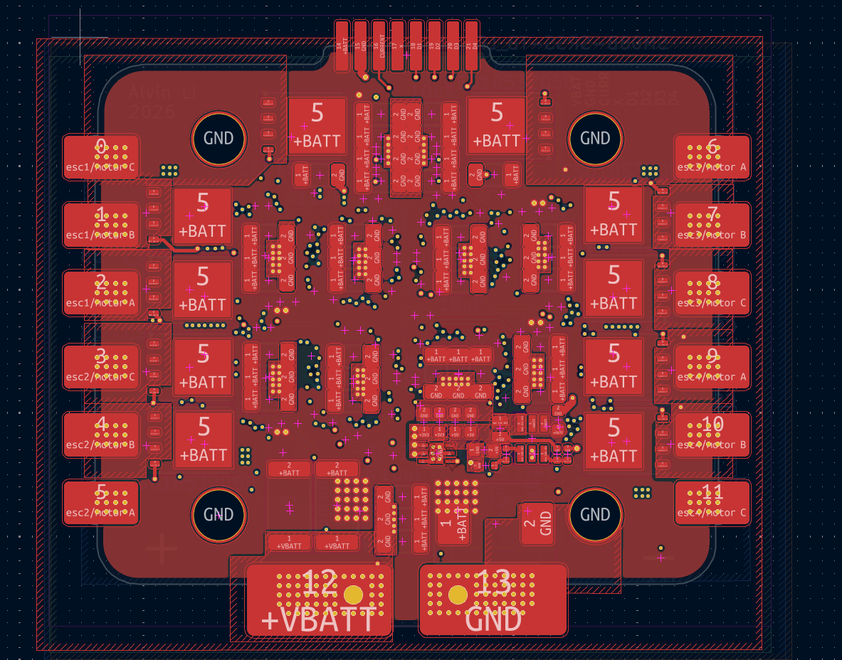 Figure: Layer 1, front copper.
Layer 2: Ground Plane
Solid ground plane beneath the top layer. Low-inductance return path for switching currents and shielding for the signal layers below. Stitched to all other ground planes with vias.
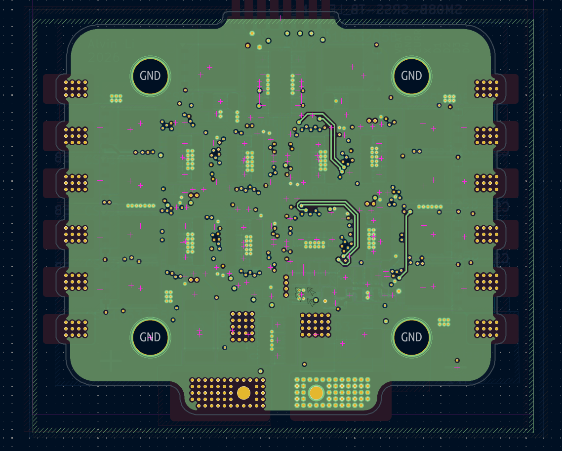 Figure: Layer 2, ground plane.
Layer 3: Power
3.3V distribution and high-current battery input and phase output traces. Wide copper pours handle peak phase currents, sandwiched between ground planes on layers 2 and 5.
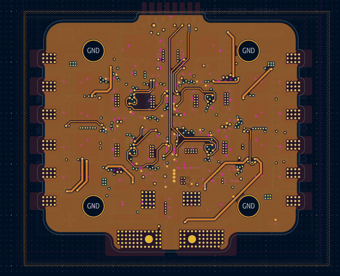 Figure: Layer 3, power routing.
Layer 4: Signal
SPI, DSHOT, PWM gate drive signals, and analog current sense lines between the DRV8323S CSA outputs and STM32 ADC inputs. Analog traces kept short and away from switching nodes.
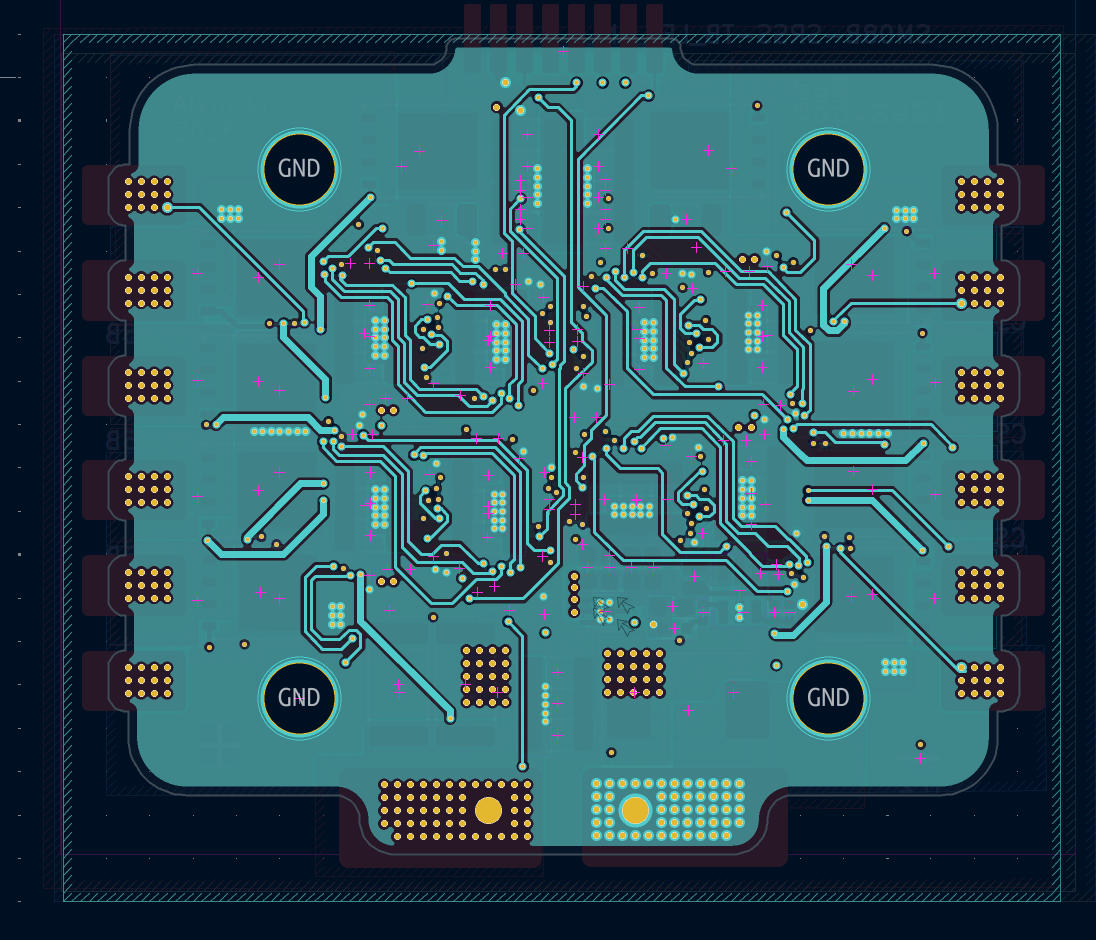 Figure: Layer 4, signal routing.
Layer 5: Ground Plane
Second ground plane sandwiching layer 3 power between two references. Return path for back-side components and shielding for layer 4 signals.
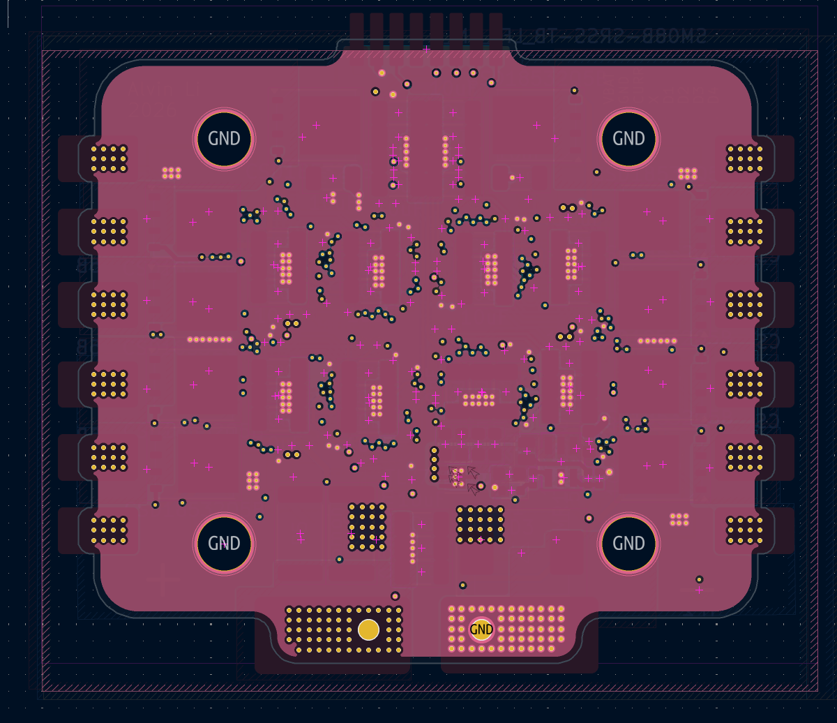 Figure: Layer 5, ground plane.
Layer 6: Back Copper (Components)
STM32G431 and DRV8323S are placed on the back, along with remaining MOSFETs, decoupling caps, and signal passives. Thermal via arrays under the DRV8323S thermal pad connect to internal copper layers for heat spreading.
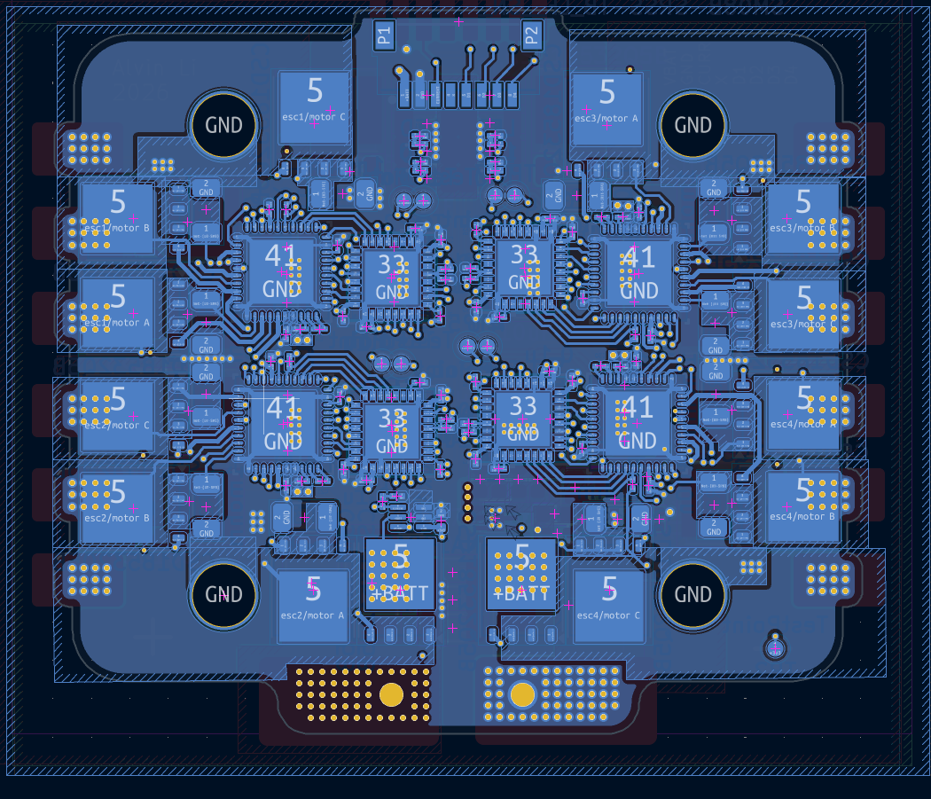 Figure: Layer 6, back copper.
3D View
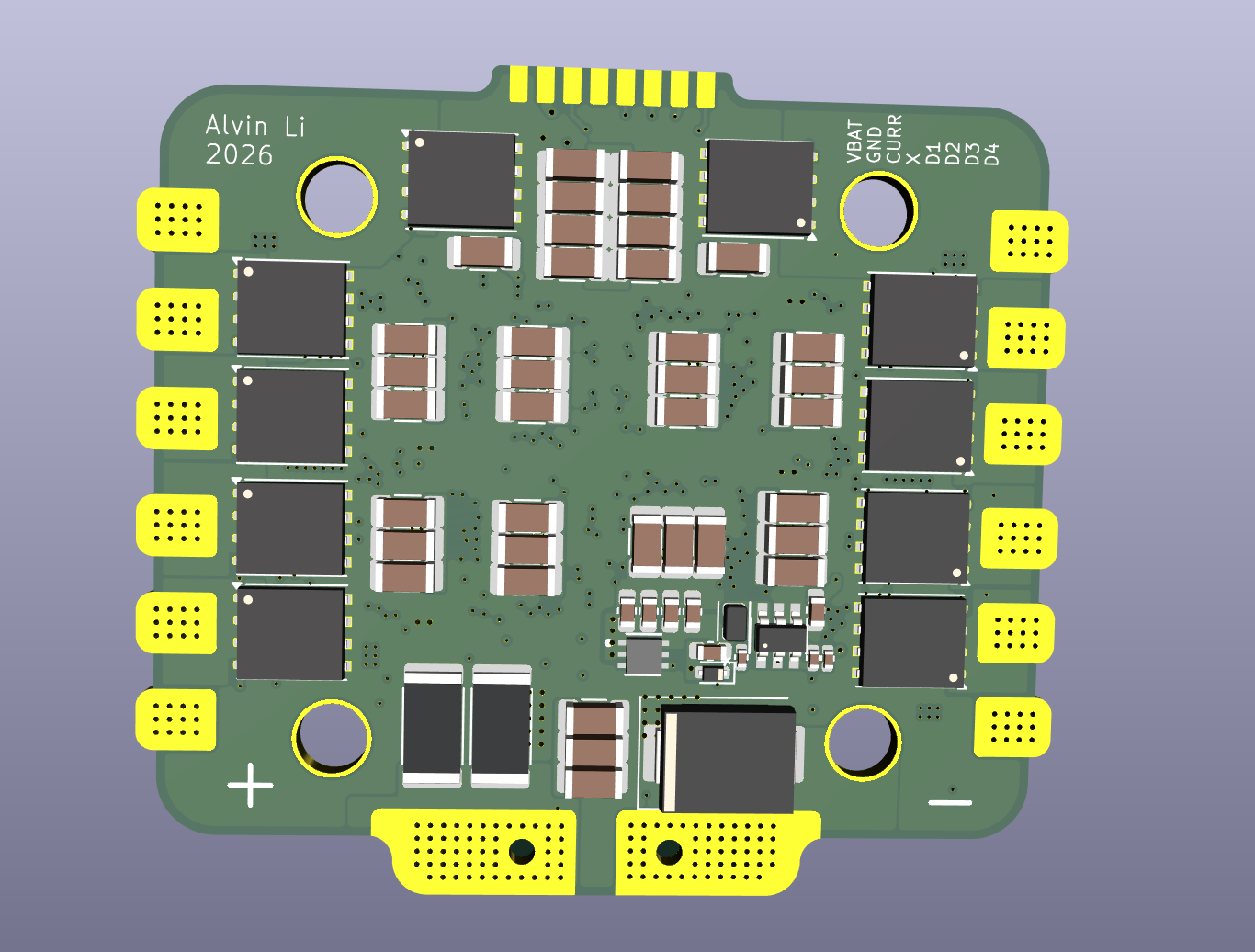 Figure: 3D render, front side. MOSFETs, gate resistors, bulk ceramics, and phase connectors.
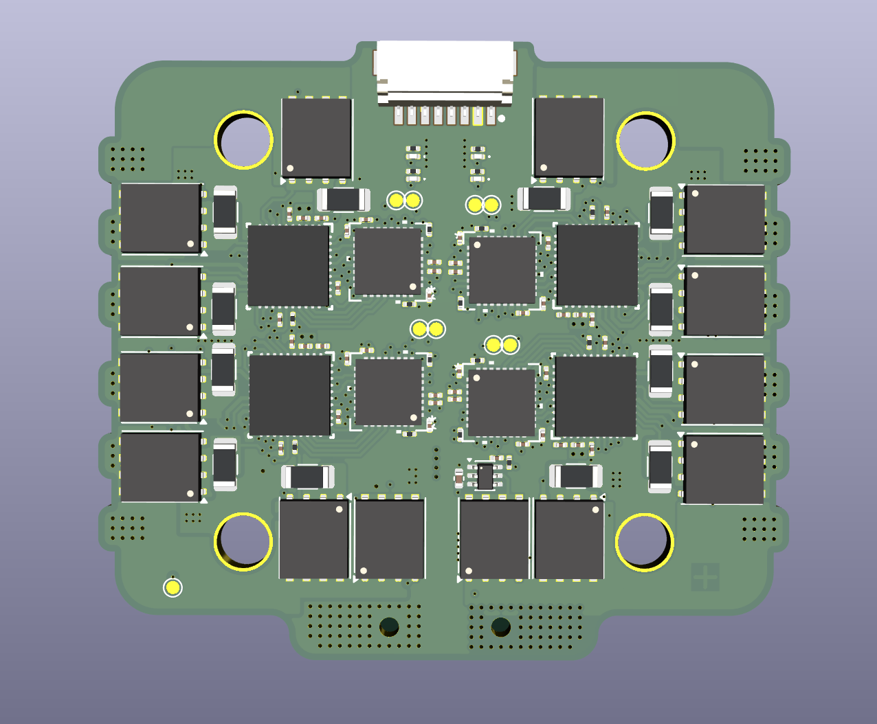 Figure: 3D render, back side. STM32G431, DRV8323S, and signal passives.
Schematics
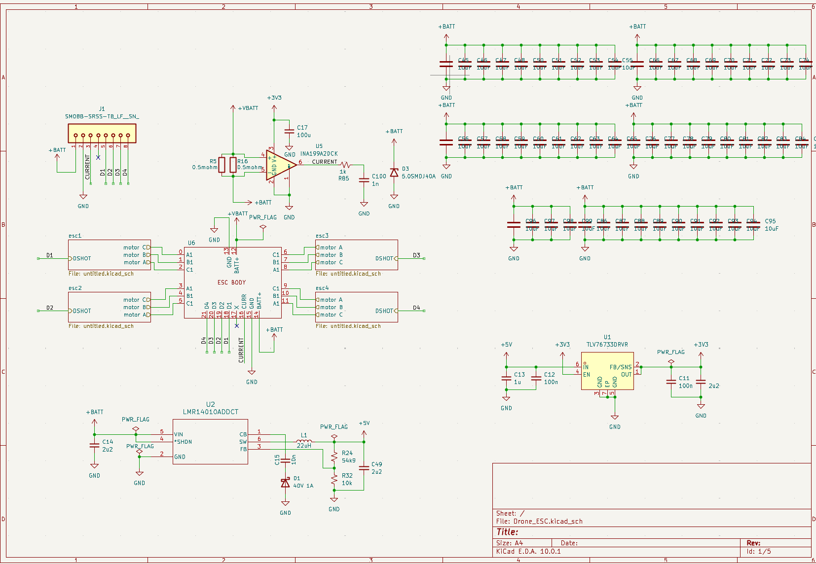 Figure: Schematic page 1.
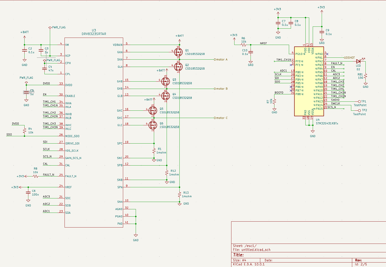 Figure: Schematic page 2.
Flight Controller
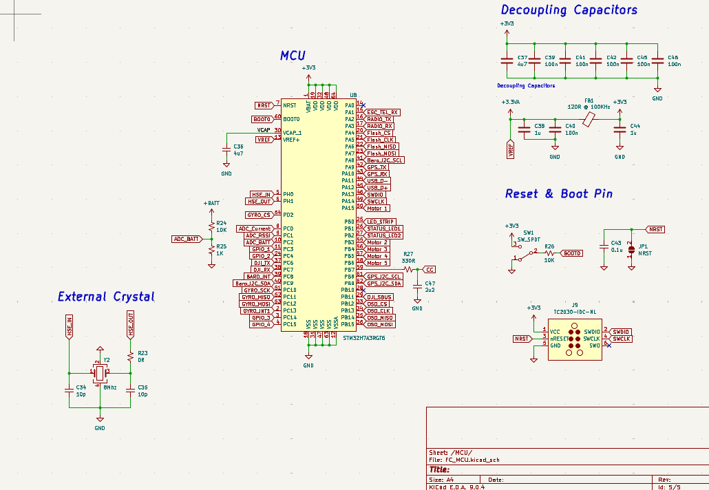
STM32H7 Based Drone Flight Controller made to interface with the ESC and includes the following features:
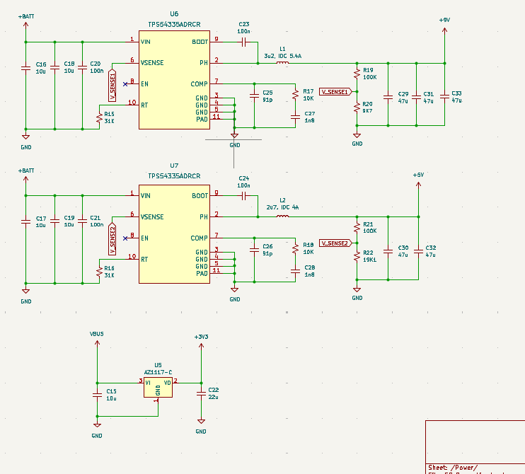
MCU - STM32H7 Interial Measurement Unit (IMU) - ICM-42688-P Barometer - BMP388 On-screen Display chip for graphical overlay (OSD) - AT7456E W25Q256JVEIQ (256 Mbit QUAD SPI NOR FLASH) for data logging +VBATT to 9V 2A Buck Converter - TPS54335ADRCR (to power camera if needed) +VBATT to 5V 2A Buck Converter - TPS54335ADRCR 5V to 3.3V 1A LDO - AZ1117-C
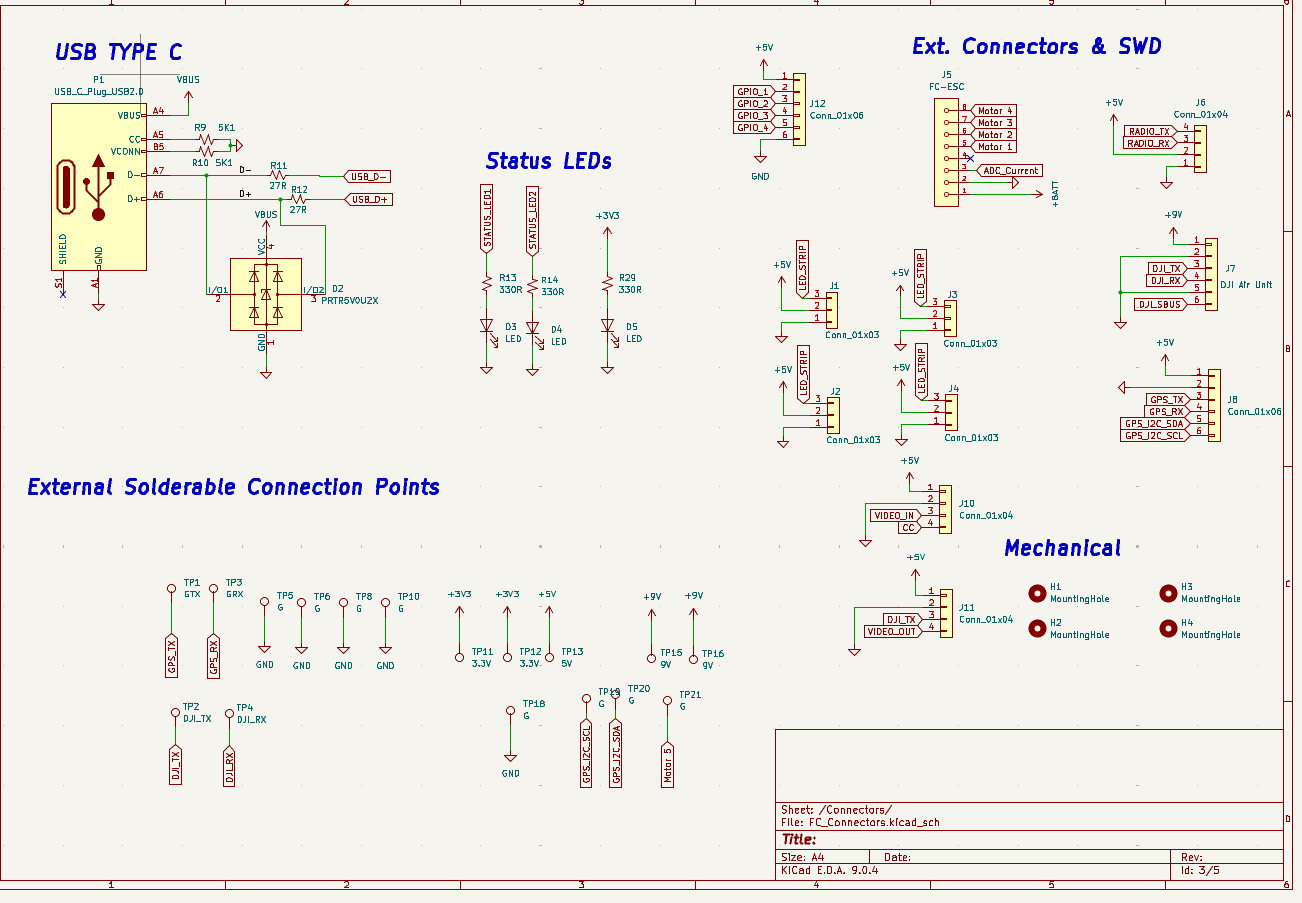
Connectors: 3 SPIs 4 UARTs 1 I2C
Sensors and Peripherals
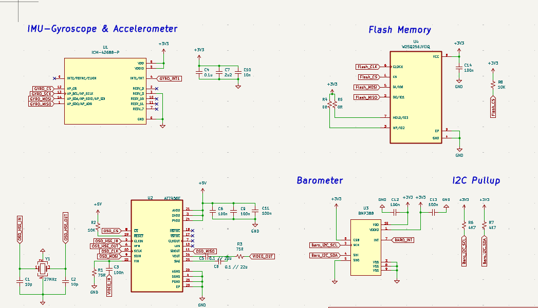
MCU
Connectors
Power
PCB Front
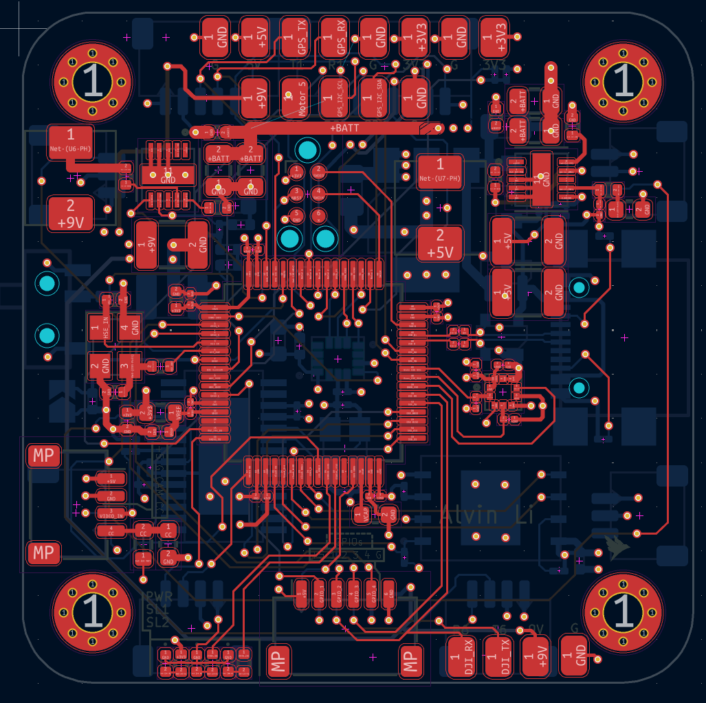
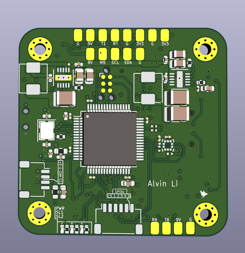
PCB Back
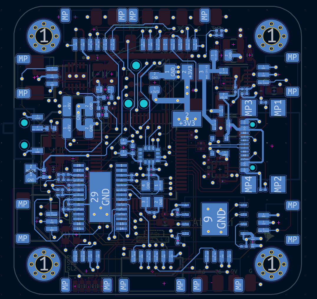
3D View
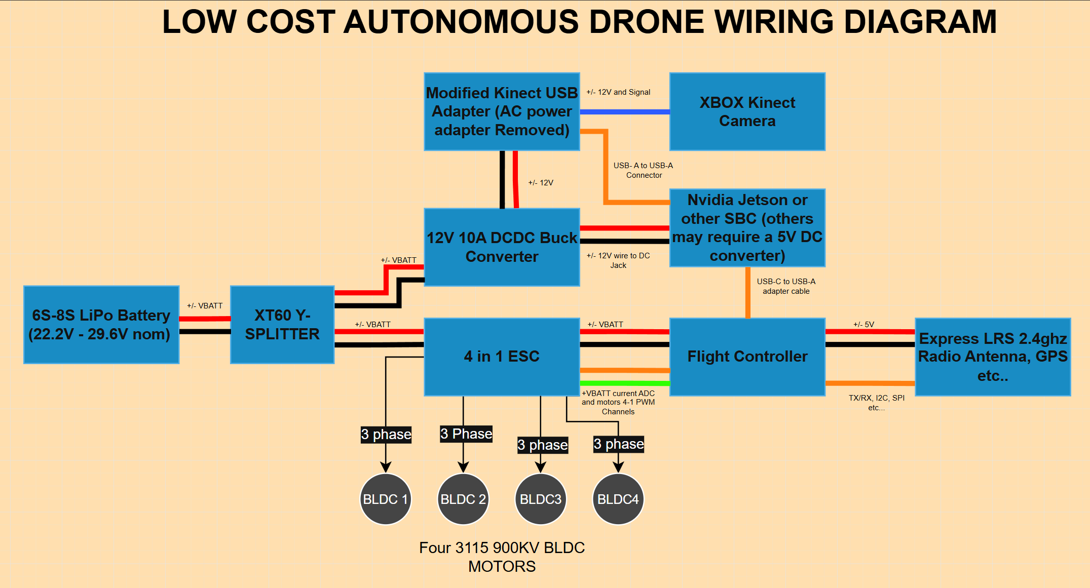
##High Level Wiring Diagram
To Power the Drone autonomously, you can setup the hardware such as this below. Other materials I have utilized include:
- 10 inch propeller MK4 carbon chassis
- 1050 three blade propellers
- XBOX Kinect 360 Camera (utilize bottom screw mounts to attach to drone). A simple 3D printed rectangle with 4 screw holes allows it to be clamped to the chassis top plate.
- 6s-8s lIPo battery
- Jetson or other SBC, such as Raspberry Pi
- 12V DCDC converter (purchased or self designed), I didn’t feel like
- XT60 Connectors soldered to the ESC. They are able to handle a continuous 80A of current, making it suitable for this application
- Y Splitter, diverts current to the DCDC and ESC XT60 connector
- 4 3115 900KV motors, the ESC has the capacity to run more powerful motors (up to 60A per driver), although these should suffice given the payload requirements (approximately 4 lb)
- Express LRS 2.4 Ghz antenna module can be soldered to the flight controller’s 5V, GND and TX/RX pads. I utilized the open source ExpressLRS library for implementing radio control in software. The antenna can interface with a common FPV drone remote control for manual control.