Filament Recycler PCB
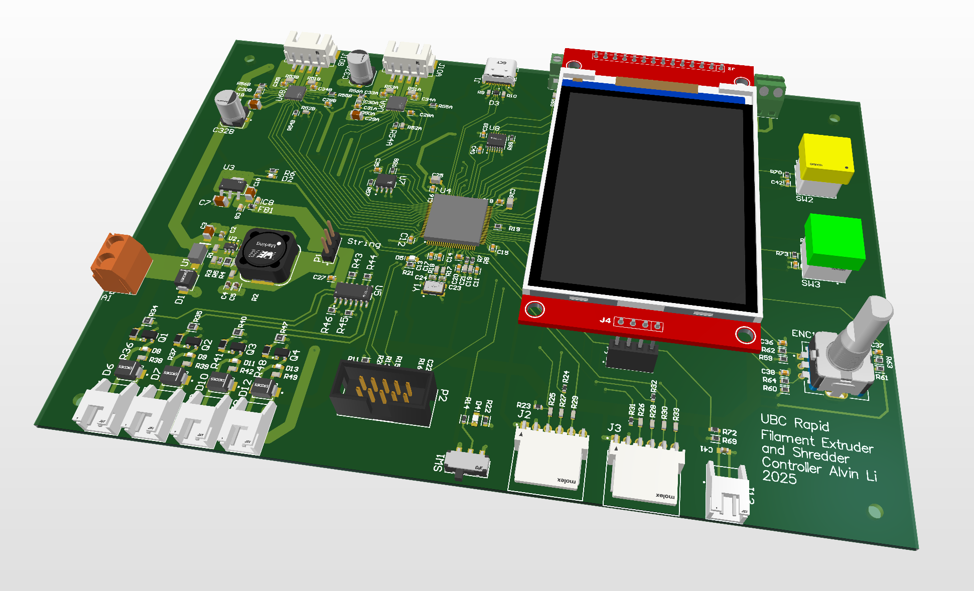
Filament Recycler PCB
As part of UBC Rapid, I designed a Filament Recycler that controls the following peripherals:
- ILI9431 SPI Display, which is compatible with the LVGL graphics library
- Buttons and Rotary Encoder
- Two TMC2209 Stepper Drivers
- Four MOSFET Based PWM 5V Fan Controllers
- EEPROM for extra memory to accommodate the graphics library
- One I2C sensor I/O, for hall effect filament diameter measuring sensor
- One SPI sensor I/O, because there were extra pins
- Logic level converter for controlling an external motor driver, for the large shredder motor
In order to power all of circuitry on this PCB, I implemented a 24V to 5V Buck Converter and a 5V to 3.3V LDO, which can provide power at 24V, 5V, and 3.3V. This PCB can also be programmed and powered through a USB-C port or serial wire debug pins.
Microcontroller and Boot Switch Schematic
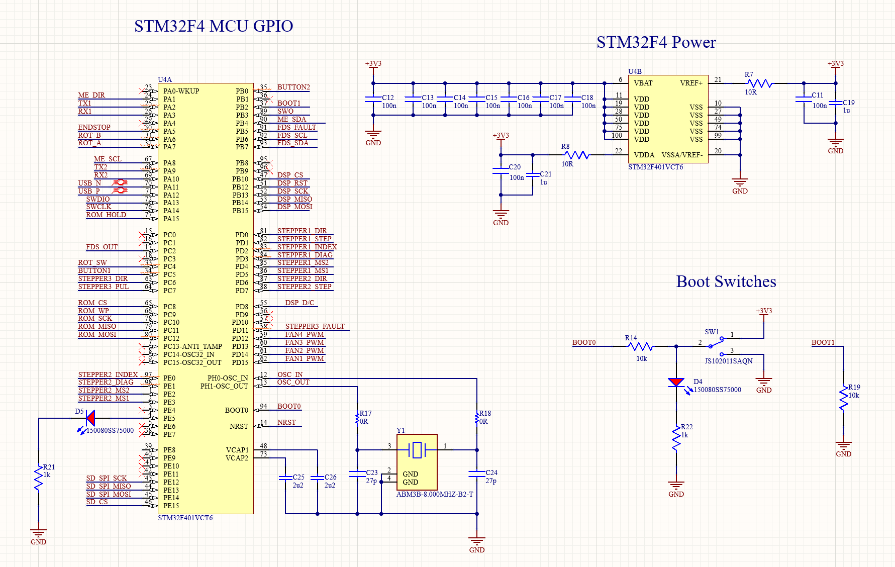
- I used an STM32F4 as the microcontroller for this project
Stepper Driver
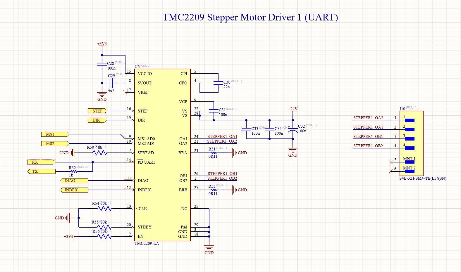
- Two TMC2209 steppermotor drivers powered by 24V input and communicates via UART to the STM32
Cooling Fans
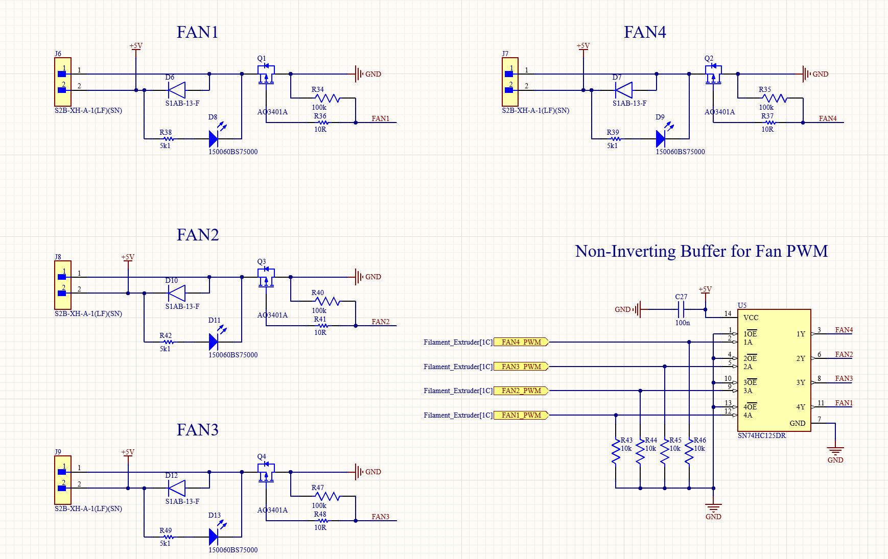
- Four 5V fans that are controlled with a PWM signal from the MCU. The 3.3V STM32F4 interfaces with the fan MOSFETS via a non-inverting buffer, which acts a relay.
- Each Fan has reverse polarity protection in the form of a diode
USB Connector
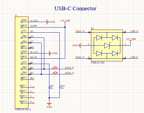
- A USB Connector with diodes for transient voltage spike protection.
Power Circuitry
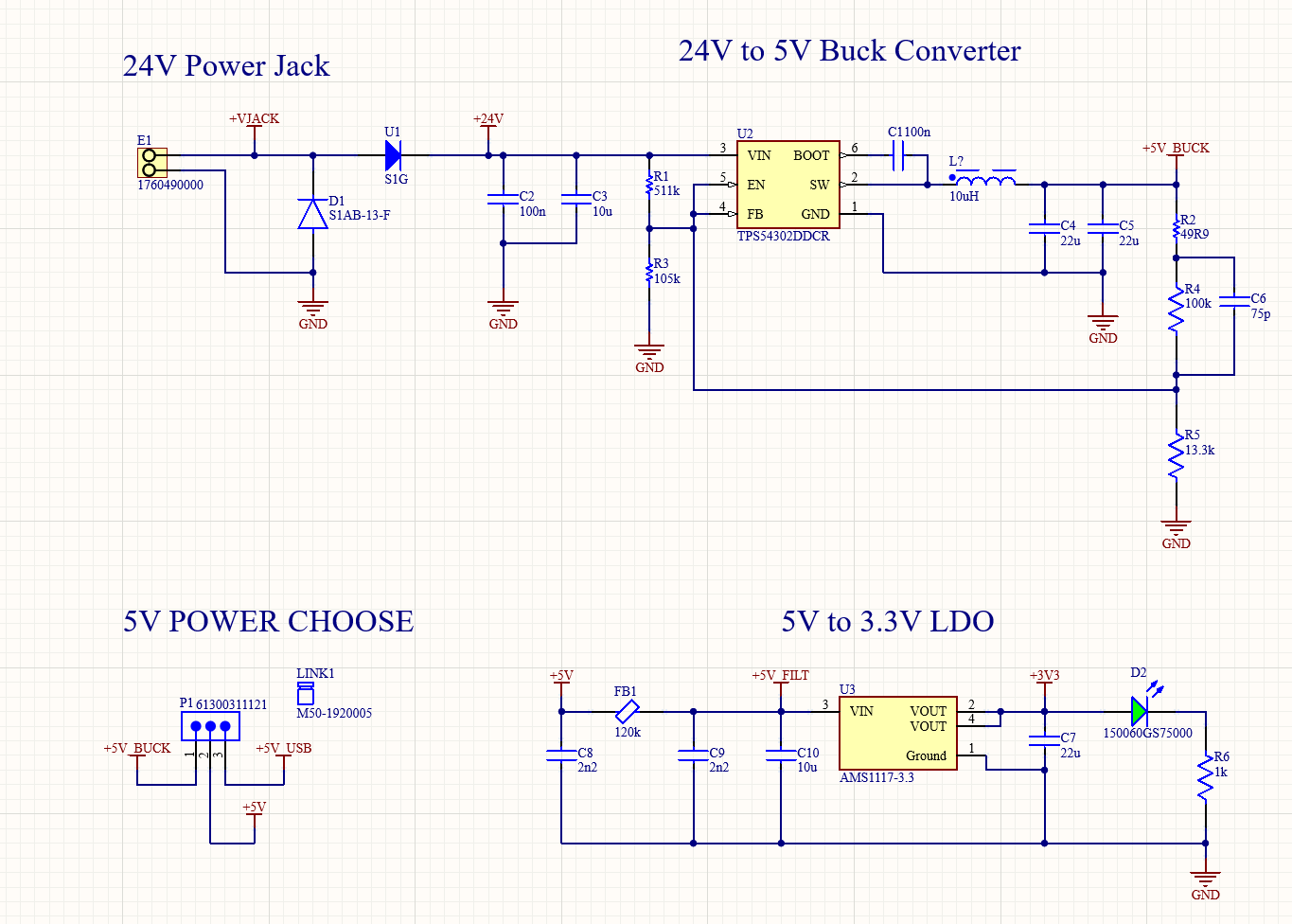
- I utilized a 24V to 5V buck converter in order to power the fans and level shifters
- The 5V to 3.3V LDO provides power to the STM32 microcontroller and other 3.3V electronics
- The power choose lets the user choose between USB and power supply power. This allows the user to run the board on either USB power or power supply power. This is a safety mechanism to prevent backfeeding in case both sources are plugged in.
EEPROM
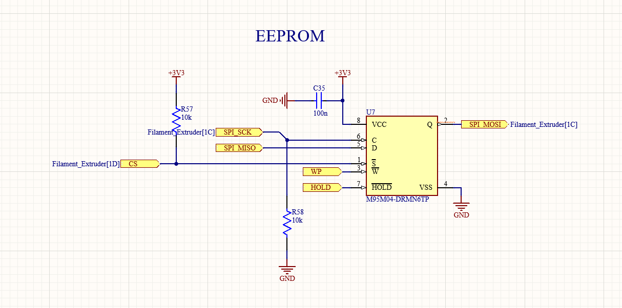
- An EEPROM allows calibration values to be stored permanentally. This allows the user to calibrate the filament diameter measurement sensor without reprogramming + flashing firmware.
- To calibrate the filament diameter sensor (Hall effect sensor), the user inserts drill bits at 1.5mm and 2.0mm, and 1.75mm diameter 3D filament into the measurement device. The firmware will record the analog voltage at those values and calculate a parabolic curve along those three different measurement values.
All circuits
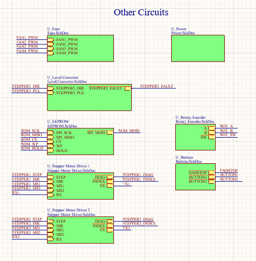
- Circuits used for the operating the GUI and other important functions, such as buttons, rotary encoders etc…
This post is licensed under CC BY 4.0 by the author.